Causing the signal to be too strong to cause distortion. In the direction that is added to the input signal or has the same phase. Or, the sounds of the feedback signal from the output to the input. When we turn the microphone towards the speaker We will hear the whistle. Which we will notice from the general audio amplifier.
Magnavox all transistor schematic how to#
We have also studied how to organize the bias circuit to have feedback. In addition to learning to connect the audio transistor. Read also: Very simple amplifier circuit using transistor 2N3904 Feedback circuit of a transistor amplifier One disadvantage is that this circuit is a simple basic tuning circuit, so it may be difficult to tune a station. Which can be heard more clearly from the radio station. Try to use headphones instead of speakers. To forward to the Q1, amplifying according to the previous principles. The diode D1 detects only the audio signal. When the values of L1 and VC1 resonance with that frequency are complete. There is an adjustable capacitor (VC1) attached to this coil. How it worksīy using the L1 coil wrapped on a ferrite rod. It is a simple experiment with an AM radio receiver circuit. This is another example of a simple Experiment 2. Related: High impedance small amplifier circuits AM radio receiver with 3 transistor amplifier circuit If the gain of each transistor is equal to 100, the total gain will be equal to (100×100) = 10,000. According to the circuit characteristics as in the Figure. We connect 2 transistors with exactly the same characteristics. See in Figure 2 shows the Darlington transistor connection. Read others: 3 transistor audio amplifier Darlington compound amplifier Figure2: Darlington compound amplifier Connection To amplify the signal once more, strong enough to drive through the speaker. Then, send it to both Q2 and Q3 that are connected to a Darlington compound amplifier circuit. But the signal is not strong enough.Īt point B. There are R1 and R2 to divide the voltage into bias to Q1. Which we set as a common emitter amplifier. And, it is transformed into a small electrical signal fed to Q1 at point A. When a sound signal comes through the MIC1. When there is an audio signal coming into the MIC1. It is an amplifier circuit from a microphone. You will hear your sound extended through the speakers. After that, try to speak on the microphone. We will hear the “popping” sound from the speaker. When finished, connect the positive and negative wires, from the 6V power supply.But be careful of the polarity of the device too. Connect the equipment according to the circuit in Figure 1 onto the breadboard.Figure1: Simple Microphone audio amplifier Circuit It will increase the single from a microphone. These circuits are simple amplifiers you can look other HERE Small transistor amplifier circuits In this experiment, it will take you to learn a simple amplifier circuit. Therefore, when using the transistor audio amplifier, the circuit works in the active phase. These two values can find the current gain (hFE) from: By driving the collector current (IC) proportional to the base current (IB). The active range is the period that the transistor operates (conducts current). Which we can limit the current flowing through the connection of the resistors.ģ. And the current will not increase any more than this. There is electricity flowing through the transistor fully Until it saturated. There will be some leakage currents which are very rare.Ģ.

Cut off ( transistor stop) There will not be both the base current (IB) and the collector (IC) flowing through the transistor. In general, we can divide the working range of the transistor into 3 ranges:ġ. Pnp 2n? see cross refer their nothing special about these transistorsġ42n9 139n2 142n10 are npn see the arrows pointing out n means plastic 2 gerinuem or crystal same as a diode discription.the first three numbers are proable bata factor 2n2222 is the same transistor.Related Posts Basic principles of transistors

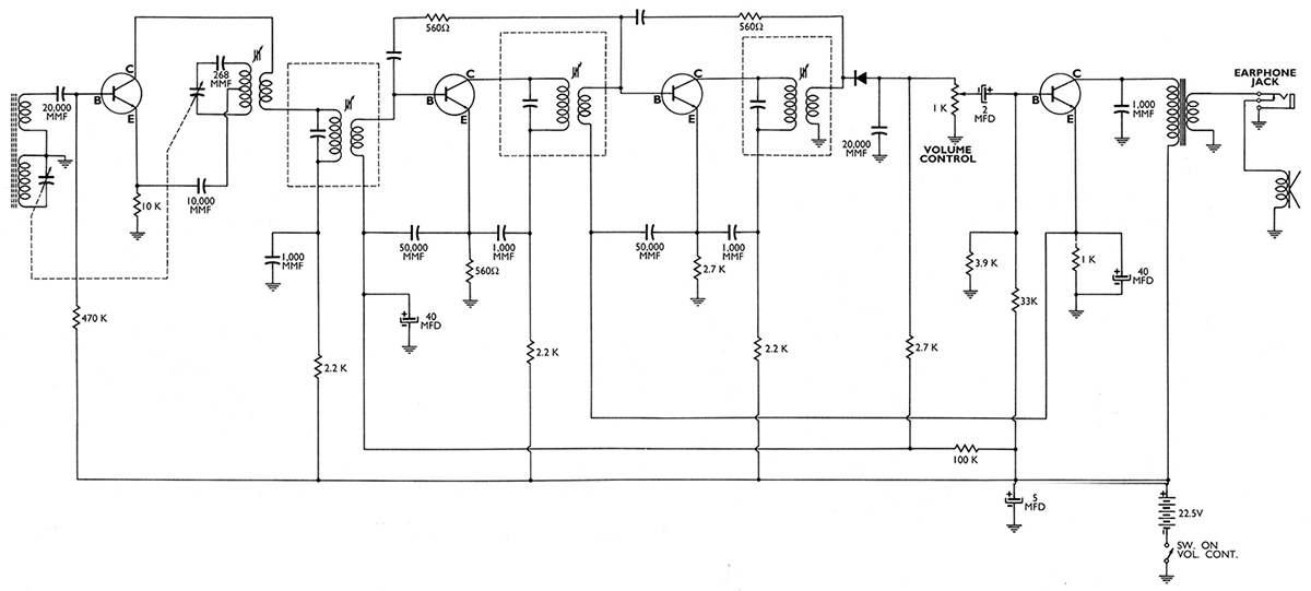
The transistor are match pairs with in 10 percent get a cheap transistor checker with lcd display match bata close to each other change in pairs close as you can. Npn arrow inside transistor drawing points out. If board is not marked ebc, or bce, etc.use transistor checker to fine base,emitter,collector if transistor your checking is bad pull another one from another circuit to check leg configuration if number on transistor is the same. watch you base, emitter, collector, configuration you may have to switch leg position i have done this they work fine. Looking at the circuits theirs appears to be only two types of circuits multivibrators or oscillators.i look at one of the photos on web their a standard plastic transistor that mfg protected numbers magnavox back then used these thinking every one is stupid.i bet you go to radio shack and buy jempack of 15pcs npn transistor and a pack of pnp transistor for a buck or two and they will work fine.


 0 kommentar(er)
